Wiring Diagram For A Fan

Ceiling Fan Wiring Diagram 1 For The Home Electrical

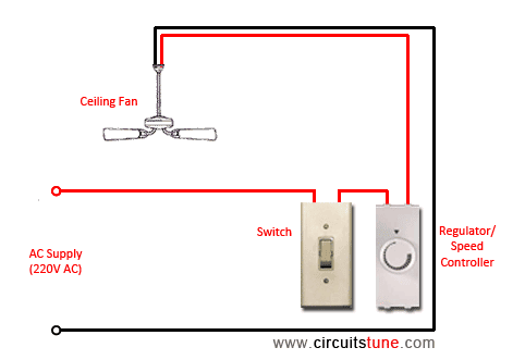
Ceiling Fan Switch Wiring Electrical 101
Ceiling Fan Wiring Diagram

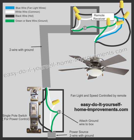
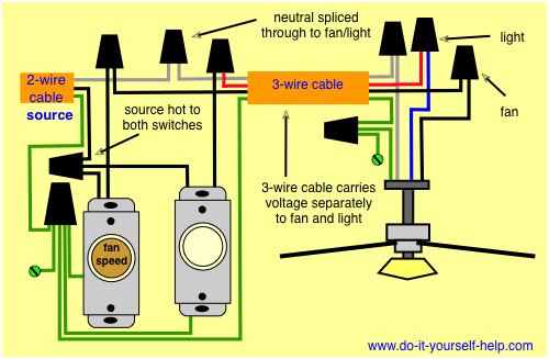
White neutral black fan blue light green ground some manufacturers may use different color codes so be sure to follow the instructions that come with your particular product.
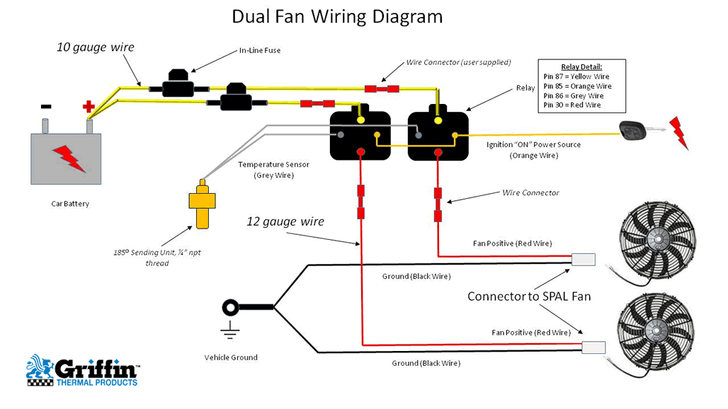
Wiring diagram for a fan. Most stand alone adjustable thermostats ie. Wiring a ceiling fan install and wire a ceiling fan ceiling fan wiring part 1 ceiling fan wiring part 2 ceiling fan wiring diagram ceiling fan wiring diagram 1 ceiling fan wiring diagram 2 ceiling fan switch single switch control for the fan and light single switch for fan and a dimmer for the light wiring a ceiling fan remote control. Hayden flex a lite or perma cool brands can provide a 12 volt output when activated. Pick the diagram that is most like the scenario you are in and see if you can wire up your fan.
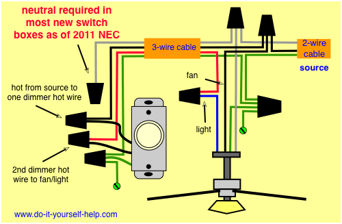
In this diagram the black wire of the ceiling fan is for the fan and the blue wire is for the light kit. This might seem intimidating but it does not have to be. Take a closer look at a ceiling fan wiring diagram. It shows the parts of the circuit as simplified forms and the power and signal links between the gadgets.
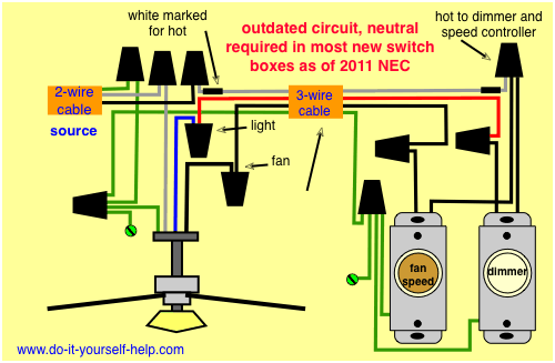
Ceiling fan wiring diagram. Ceiling fan with light kit wiring diagram this wiring diagram illustrates the connections for a ceiling fan and light with two switches a speed controller for the fan and a dimmer for the lights. A wiring diagram is a simplified traditional pictorial representation of an electrical circuit. The fan control switch usually connects to the black wire and the light kit switch to the red wire of the 3 way cable.
With these diagrams below it will take the guess work out. The source is at the switches and the input of each is spliced to the black source wire with a wire nut. Suggested electric fan wiring diagrams suggested primary cooling fan single speed onoff using 12 volt switching devices only for primary activation note.

New Industrial Exhaust Fan Wiring Diagram Diagram
Wiring Diagrams For A Ceiling Fan And Light Kit Do It
Dual Fan Wiring Diagram
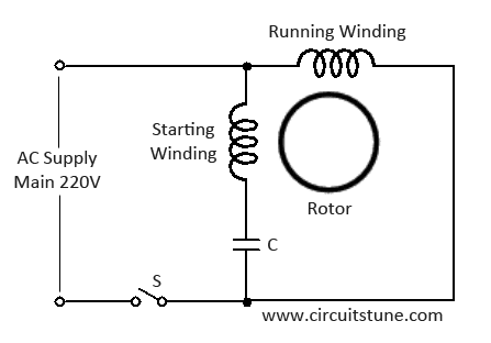
Ceiling Fan Wiring Diagram With Capacitor Connection

Wiring A Ceiling Fan And Light Pro Tool Reviews
Ceiling Fan Wiring Diagram With Capacitor Connection

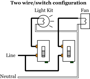
Ceiling Fan Wiring Diagram Two Switches

Fantasia Fans Fantasia Ceiling Fans Wiring Information
Wiring Diagrams For A Ceiling Fan And Light Kit Do It

Wire A Ceiling Fan

Cooling Fans Wiring Diagram

Wiring Dual Electric Fans
Ceiling Fan Switch Wiring Electrical 101
Wiring Diagrams For A Ceiling Fan And Light Kit Do It

Install Shower Extractor Fan Electrics
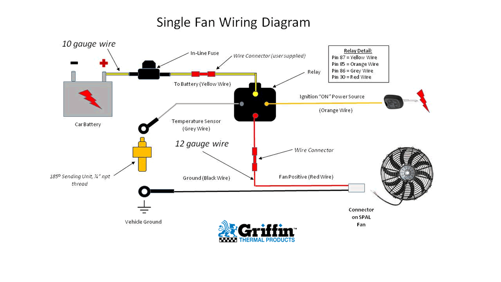
Single Fan Wiring Diagram
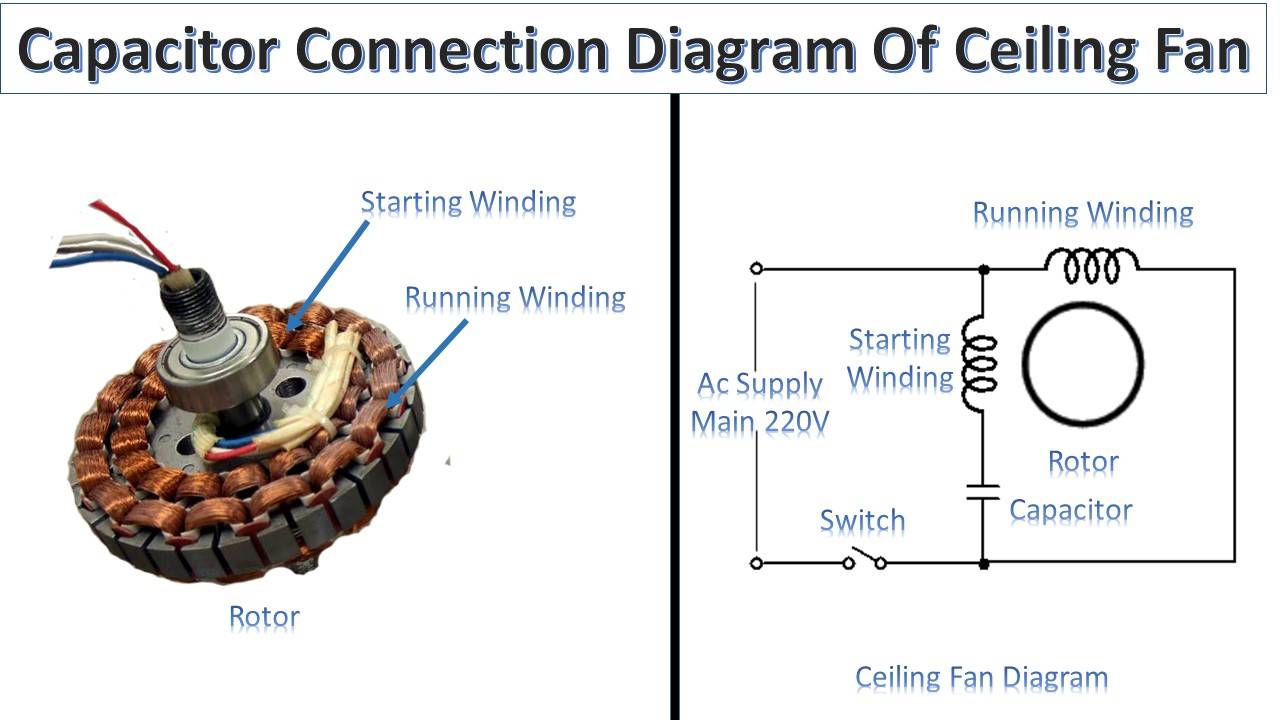
Capacitor Connection Of Ceiling Fan Earth Bondhon
Wiring Diagrams For A Ceiling Fan And Light Kit Do It

Fan Limit Control Installation Faqs

Ceiling Fan 3 Speed Switch Cryptoletter Co

How To Wire Dual Electric Cooling Fans Roadkill Customs
