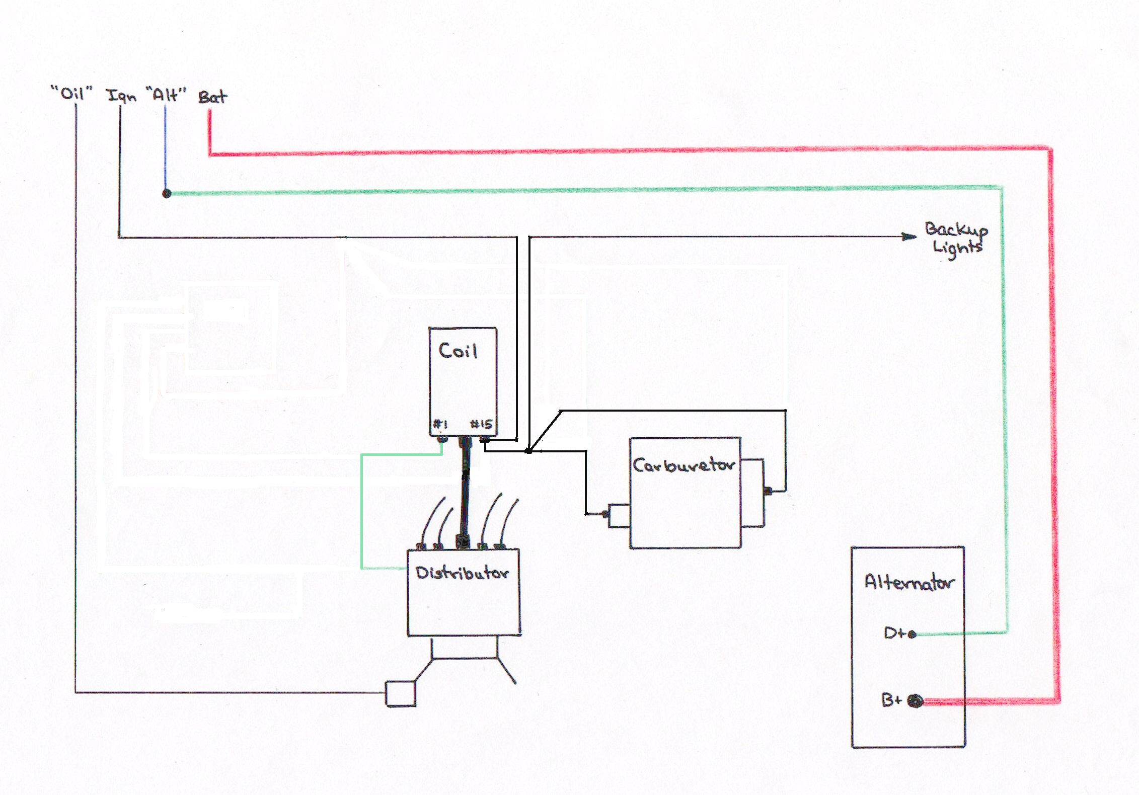
Voltage Regulator Wiring Schematic

Sample Image Ford Alternator Wiring Diagram Internal

Wiring Diagram Ford Voltage Regulator Wiring Diagram

Ford Regulator Wiring Wiring Schematic Diagram

The article was submitted by mr.
Voltage regulator wiring schematic. 6 wire voltage regulator wiring diagram welcome to our site this is images about 6 wire voltage regulator wiring diagram posted by benson fannie in 6 category on oct 07 2019. Im resurrecting this thread after some trouble. Going back to original postings before. Contents hide 1 technical specifications 11 understanding.
Bottom line up front. Lm317 is a three terminal adjustable regulator from national semiconductors and its input can range up to 40 volts. Collection of automotive voltage regulator wiring diagram. Well this is a collection of voltage regulator circuits using the lm317 ic which is an adjustable voltage regulator.
Fluctuation in voltage can harm these electrical mechanisms. Six volt generators and 12 volt alternators require current at voltages. It reveals the components of the circuit as simplified forms and also the power and also signal links between the tools. Adjustable voltage regulator circuit using lm317.
The article provides a detailed explanation regarding the various voltage regulator wiring configurations used in motorcycles. A wiring diagram is a streamlined standard photographic representation of an electric circuit. Alternator wiring diagrams and information brianesser in 4 wire voltage regulator wiring diagram image size 480 x 320 px image source. You can also find other images like images wiring diagram images parts diagram images replacement parts images electrical diagram images repair manuals images engine diagram images engine scheme diagram images.
A tractors regulator takes the voltage provided by the battery manages it. A voltage regulator takes current from a battery with oscillating voltage and puts out constant voltage.
Alternator Voltage Regulator Wiring Ford Truck Enthusiasts
Alternator Wiring With And Without The Dash Warning Light

Voltage Regulator Wiring Diagram Ford Best Of External Fresh

Ford Regulator Wiring Wiring Schematic Diagram
Mopar Charging Systems

Wiring Diagram Ford Voltage Regulator Wiring Diagram
6 Pin Voltage Regulator Wiring Help Page 2 Ih8mud Forum
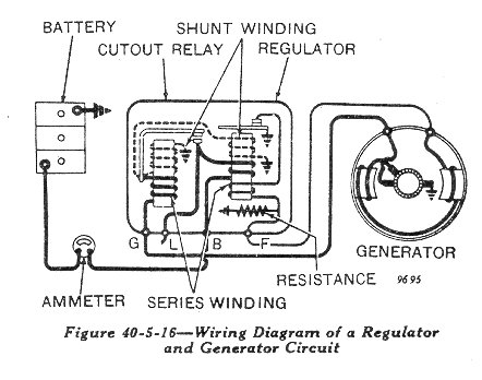
The Wiring On The John Deere Model B

Wiring Diagram Ford Voltage Regulator Wiring Diagram
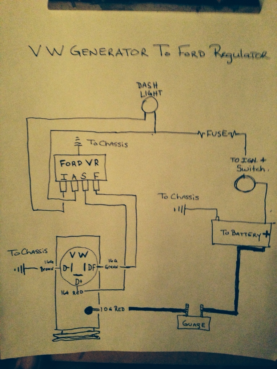
Vw Regulator Wiring Wiring Schematic Diagram

Gm Alternator To Voltage Regulator Wiring Diagram

1967 Vw Voltage Regulator Wiring Diagram Wiring Schematic

Wiring Diagram Of Alternator And Voltage Regulator Wiring

Motorola Voltage Regulator Wiring Diagram Swift Electrical
Alternator Wiring

Kohler Engine Electrical Diagram Re Voltage Regulator

Delco Alt Regulator Wiring Wiring Diagrams Folder
Ford Alternator Wiring Diagram Internal Regulator
6 Pin Voltage Regulator Wiring Help Page 2 Ih8mud Forum

Figure 1 10 Wiring Schematic Diagram Voltage Regulator

Ford Alternator Wiring Diagrams
