Marine Wiring Schematic
How To Wire A Boat Beginners Guide With Diagrams New

Boat Wiring Schematic Boat Boat Wiring Boat Building

Boat Building Standards Basic Electricity Wiring Your Boat

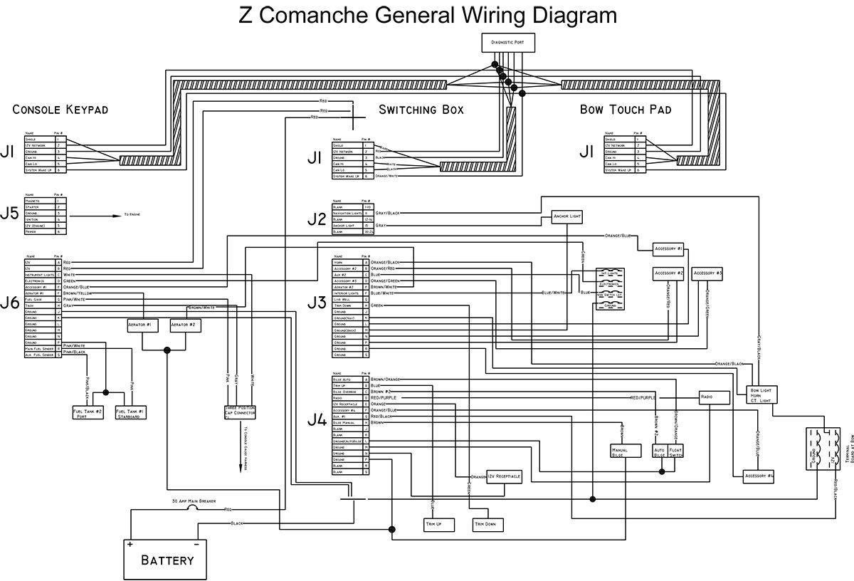
Equipment coming off a switchboard or circuit panel should be straightforward to trace.
Marine wiring schematic. For additional boat wiring and marine electrical information. Circuitry layouts are made up of two things. Wiring diagrams for most popular boats supplied by marine electrical products. Wiring schematics for baymaster boats.
The lack of boat wiring diagrams. West marine is committed to outfitting your life on the water. Example of a draft wiring diagram for a simple boat. Wiring diagrams page 1.
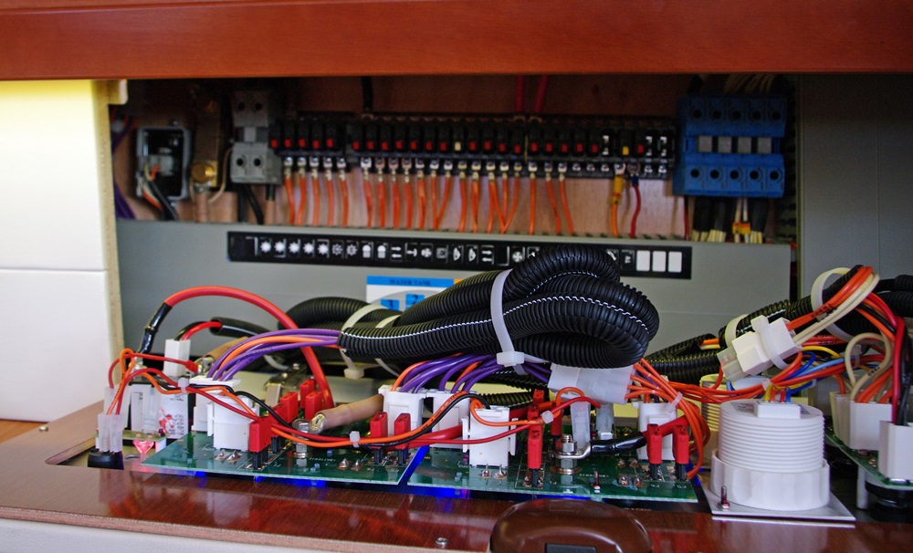
We have wiring diagrams and wiring guides on how to wire a 10 terminal navancher on off on 3 way carling contura rocker switch as well as a wiring diagrams in how to wire a 10 terminal bilge auto manual on off on 3 way carling contura rocker switch for. Wiring schematics pictures best practices and tips to get your boats electrical systems in shape. Wiring schematics pictures best practices and tips to get your boats electrical systems in shape. The regular use of non standard and non traceable boat wire colors.
Wiring diagrams marine electrical products. When you make your own wiring diagram use very large sheets of paper for clarity. Or worse the all too common practice of wiring an entire boat with only one color of marine electic wire. Wiring schematics for challenger boats.
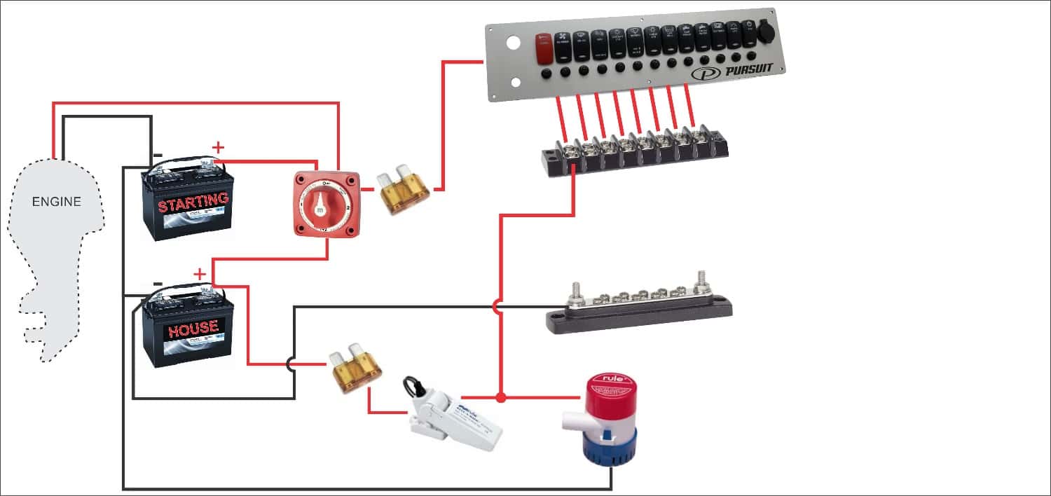
Shop with confidence get free shipping to home or stores price match guarantee. Wiring schematics for g3 boats. The section below has wiring diagrams the are specific to marine rocker switch panels. I need a simple wiring diagram for a small outboard boat to wire up the lights and few other things but no one seems to have one.
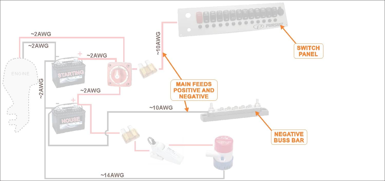
The basics of boat wiring. Consult an abyc certified marine electrical professional for system design and circuit protection. A question often asked on boating and boat building forums and of me by visitors to my web site is. With over 250 store locations 100000 products in stock and knowledgeable associates trust west marine for your boating sailing fishing or paddling needs.
And other ezacdc boat wiring components. A wiring diagram is a type of schematic which utilizes abstract pictorial icons to reveal all the interconnections of components in a system. Most boats will have positive and negative busses where area wires come together. Icons that represent the parts in the circuit and also lines that stand for the connections in between them.
The basics of boat wiring.
10 Basic Rules For Wiring A Boat Wired2fish Com

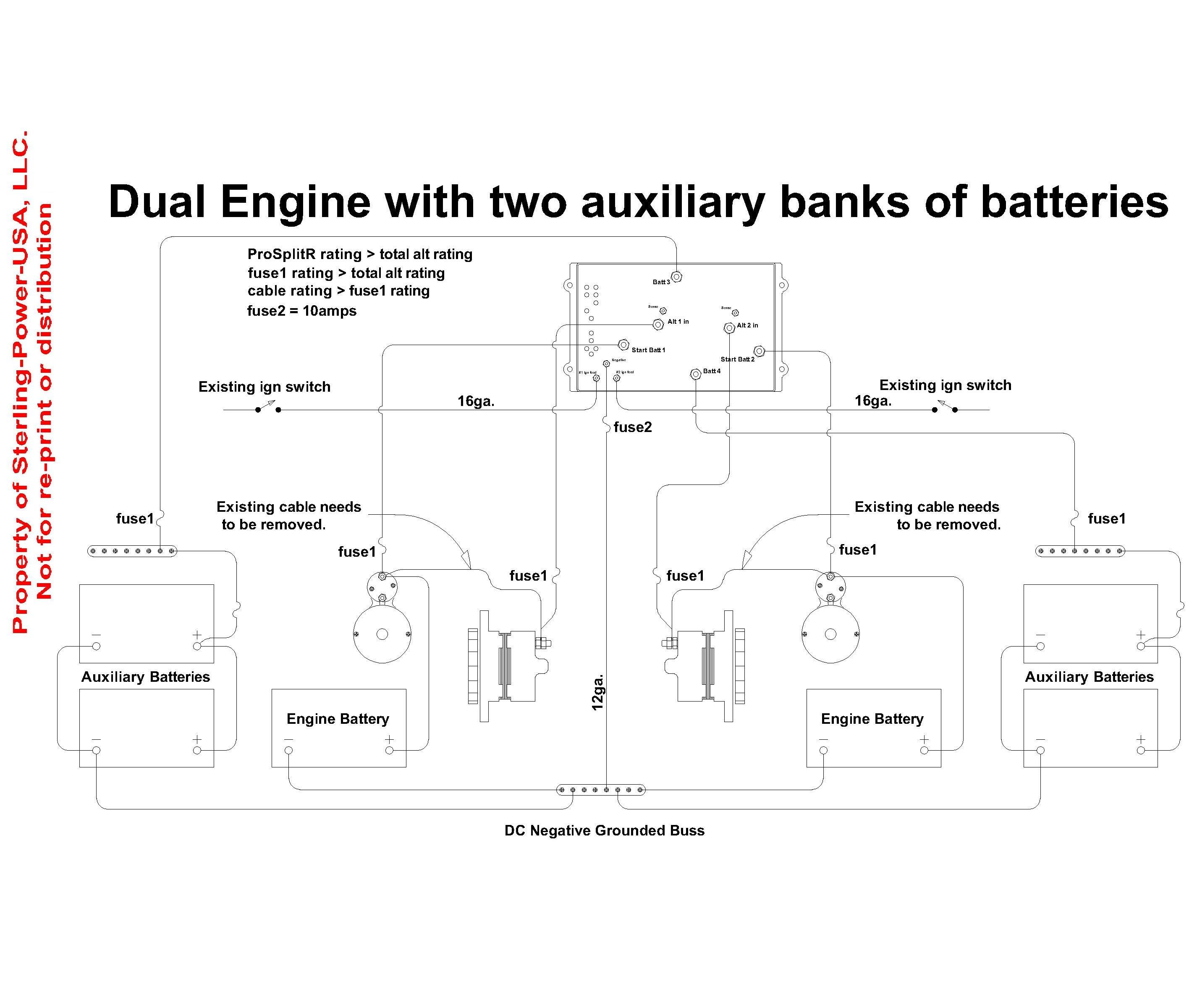
Battery Management Wiring Schematics For Typical
Create Your Own Wiring Diagram Boatus Magazine

Battery Management Wiring Schematics For Typical
Software To Document Boat Wiring The Hull Truth Boating

Boat Wiring Diagram Boat Trailer Lights Boat Wiring Boat

How To Wire A Boat Beginners Guide With Diagrams New
Sailboat Wiring Diagram Wiring Schematic Diagram
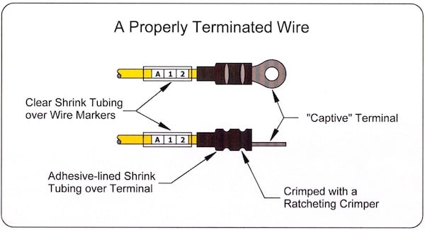
Boat Project 30 Tips For Better Boat Electrical Systems

0 Rc Boat Wiring Diagram Organized Circuit Library
Starcraft Boat Wiring Diagram Wiring Diagram
12 Volt Basics For Boaters Boats Com

Esper Refit 36 Simple Boat Wiring Followtheboat
Wiring Diagrams Literature For Pro Charge Ultra Marine

Champion 171 Bass Boat Wiring Diagram Wiring Diagrams Folder

Pontoon Wiring Diagrams Wiring Diagram
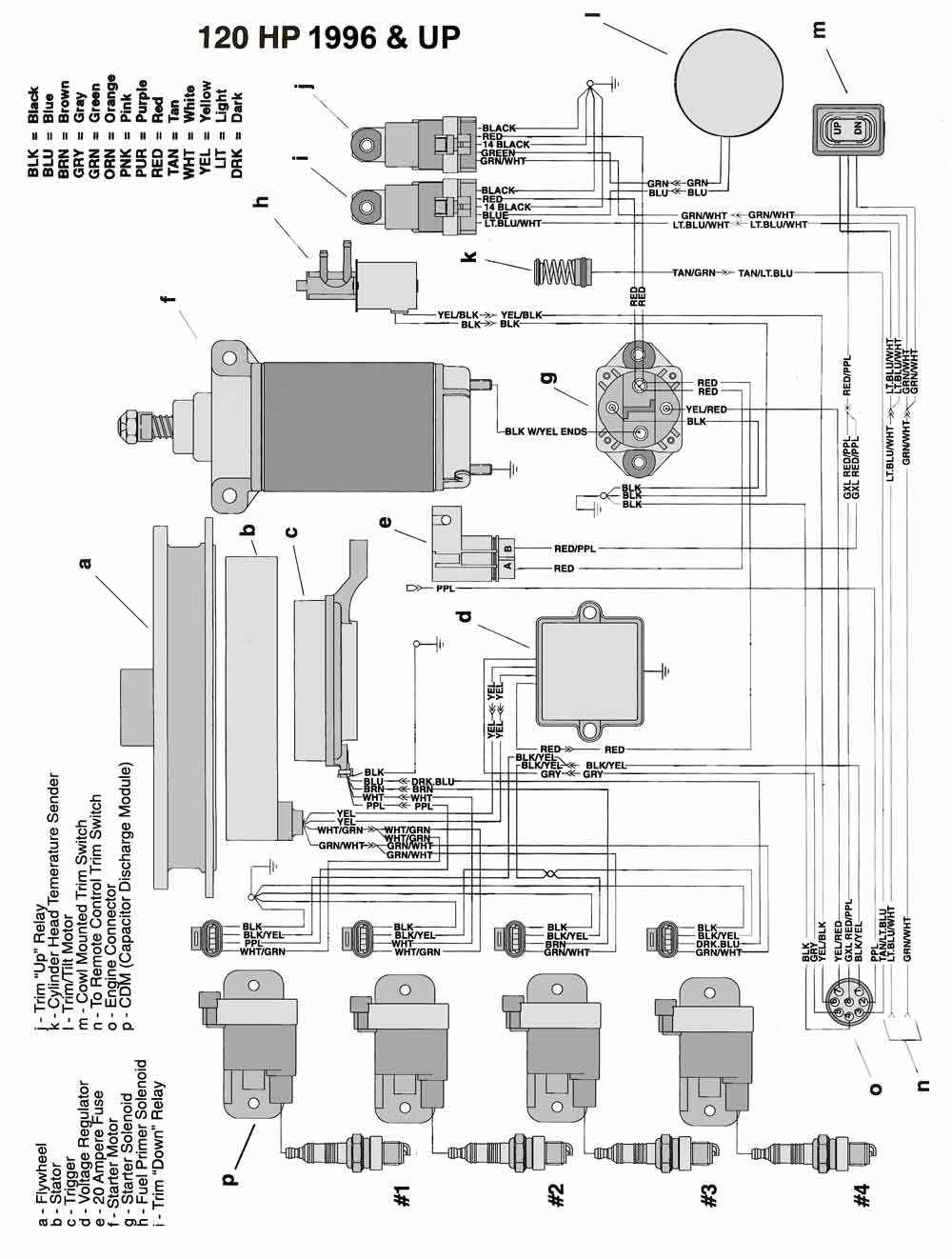
Mastertech Marine Chrysler Force Outboard Wiring Diagrams

Maxwell

Troubleshooting Teleflex Fuel Gauges
Wiring Diagram Starcraft Boat Schematics Online
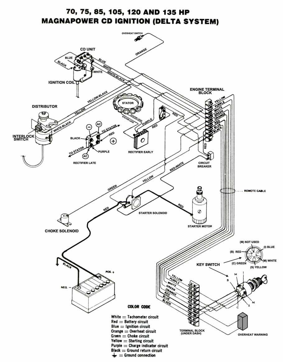
Mastertech Marine Chrysler Force Outboard Wiring Diagrams
