Industrial Electrical Wiring Diagram

How To Construct Wiring Diagrams Industrial Controls

Electrical Print Reading Industrial Wiki Odesie By Tech

Industrial Building Electrical Wiring Diagrams Wiring Diagram
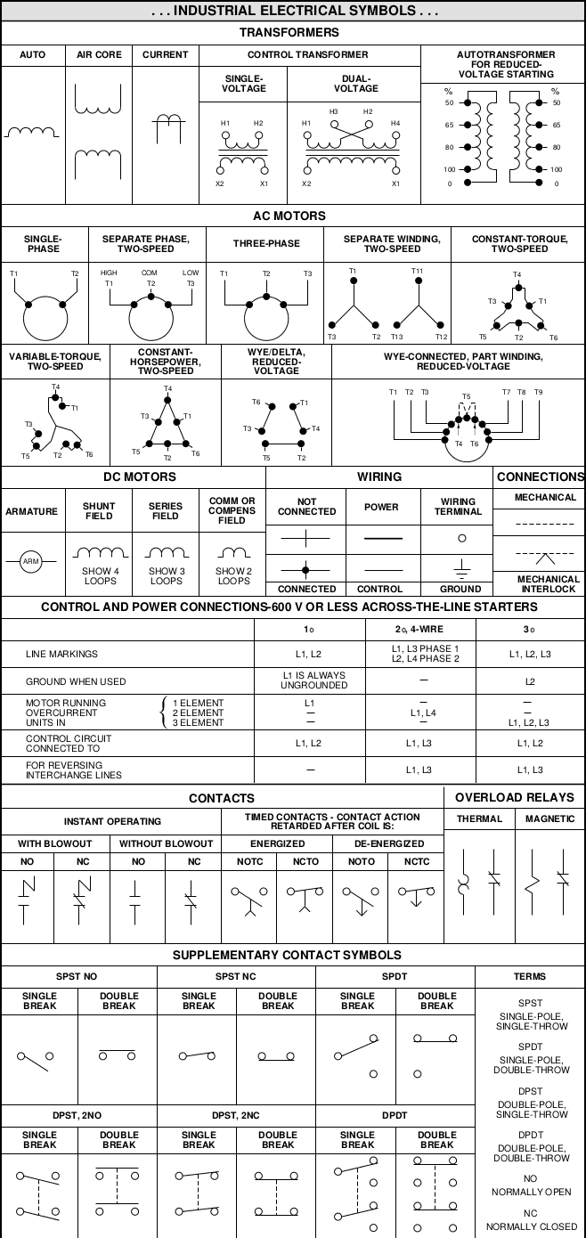
The standard electrical symbols are smart industrial standard and vector based for electrical schematic diagrams.
Industrial electrical wiring diagram. Because every type of machine has unique requirements for wiring methods operator safety depends on your understanding the differences between rules in the nec and methods outlined in nfpa 79every type of machine has unique requirements when it comes to operator safety. A wiring diagram is a simple visual representation of the physical connections and physical layout of an electrical system or circuit. Wiring diagrams help technicians to see how the controls are wired to the system. Many people can read and understand schematics known as label or line diagrams.
Most of electrical symbols can change their appearance style and color according to the requirement. This learning system will. When and how to use a wiring diagram. There are various types of diagrams that a technician may find useful in different aspects of their work.
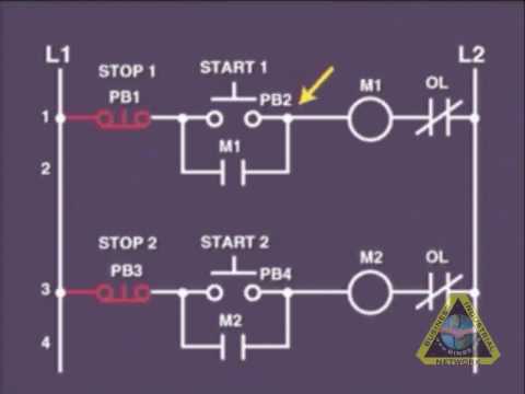
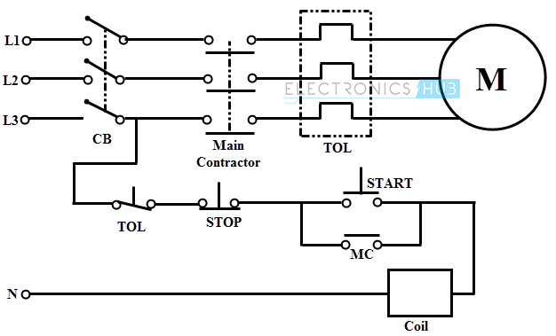
Electrical wiring diagrams of a plc panel. This type of diagram is like taking a photograph of the parts and wires all connected up. To understand how to read ladder wiring diagrams lets start with a simple electrical schematic consisting of a power supply switch and light then you will move on to our control panel sample wiring diagrams. The electrical design for each machine must include at least the following components.
Lets start with the page and line numbering. Basics of electrical wiring such as wire termination wire sizing conduit sizing termi. First of all most modern north american industrial control system wiring diagrams have a relatively common numbering scheme and once you understand the scheme it makes it fairly easy to navigate the wiring diagram commonly called a print set. Basic electrical home wiring diagrams tutorials ups inverter wiring diagrams connection solar panel wiring installation diagrams batteries wiring connections and diagrams single phase three phase wiring diagrams 1 phase 3 phase wiringthree phase motor power control wiring diagrams.
From an electrical standpoint industrial machine equipment and tools from drill presses to. Some are like simple road maps in that they show where components are physically located the wire paths between components and connection points. Industrial electrical wiring learning system 85 mt6 back of the 85 mt6. These diagrams show the actual location of parts color of wires and how they are connected.
In an industrial setting a plc is not simply plugged into a wall socket.

How To Construct Wiring Diagrams Industrial Controls

Industrial Electrical Symbol Chart In 2019 Electrical
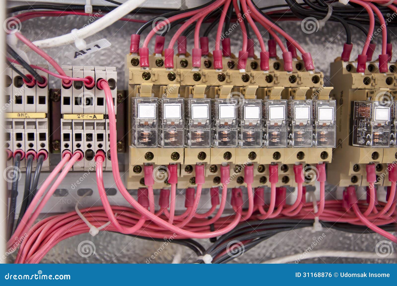
Electrical Wiring Control Panel Diagram Stock Photo Image

Pin By Diagram Bacamajalah On Technical Ideas Electrical

Wiring Diagram Standards Malochicolove Com
Electrical Wiring Electrical Circuits Wiring Tutorial

Electrical Wiring Diagram Switches Symbols Electrical
Electrical Wiring Systems And Methods Of Electrical Wiring

Electrical And Electronic Drawing Industrial Controls

How To Read Control Panel Schematic Drawings

Diagrams Of Electrical Circuits Zen Diagram Schemaw
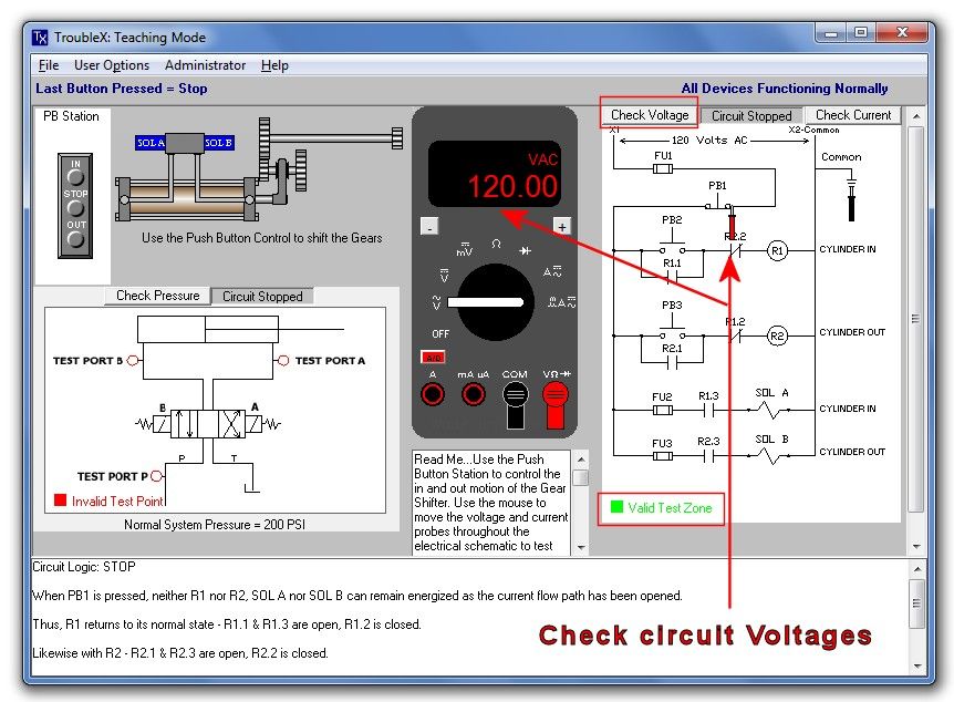
Fundamental Electrical Troubleshooting Industrial

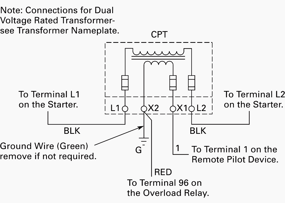
Submersible Pump Wiring Diagram With Electric Control Box

Electrical Diagrams Marcha Paro Cool Ideas In 2019

Images Of Reading Electrical Wiring Diagrams Wire Diagram
Industrial Electrical Wiring Diagrams 480v 277v Power Light
Industrial Electrical Symbols

Basic Home Wiring Plans And Diagrams Diagram House

Basic Industrial Electrical Wiring Diagrams Wiring Library
Logic Block Diagram Wiring Diagrams Folder

Industrial Wiring Diagrams Bcberhampur Org
