Different Wiring Diagram
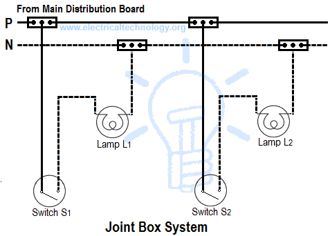
Types Of Wiring Systems And Methods Of Electrical Wiring

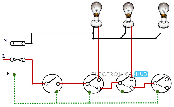
Do Staircase Wiring With 3 Different Methods Electrical
Types Of Electrical Wiring

Green or bare wire is the ground wire.
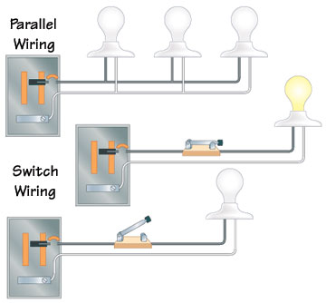
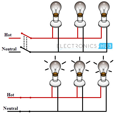
Different wiring diagram. This might seem intimidating but it does not have to be. This diagram illustrates wiring for one switch to control 2 or more lights. The hot and neutral terminals on each fixture are spliced with a pigtail to the circuit wires which then continue on to the next light. 3 way switch wiring diagram.
It shows how the electrical wires are interconnected and can also show where fixtures and components may be connected to the system. Pick the diagram that is most like the scenario you are in and see if you can wire your switch. A wiring diagram is the most common form of electrical wiring diagram. The source is at sw1 and 2 wire cable runs from there to the fixtures.
A wiring diagram is a simple visual representation of the physical connections and physical layout of an electrical system or circuit. They are crucial to the assembly of the circuit or system. Wiring and equipment on the wiring diagram is carefully laid out to show the approximate location of equipment in the circuit and thus within the home. Find a repair manual for your car get instant access to your vehicles drive belt routing complete wiring diagrams trouble code information and other available updates and factory bulletins with online auto repair manuals.
The individual wires on the diagram should be colored the same as the actual wires you will be using. Unlike a schematic its concerned with the connections between the different parts of a circuit or parts of an entire electrical system. Multiple light wiring diagram. With these diagrams below it will take the guess work out of wiring.
Wiring diagrams or layouts illustrate the physical connections or wiring between components. White wire or off white is neutral. Take a closer look at a 3 way switch wiring diagram.

Staircase Wiring Circuit Diagram How To Control A Lamp
Electrical Wiring Systems And Methods Of Electrical Wiring
Electrical Wiring Systems And Methods Of Electrical Wiring
3 Different Types Of Electrical Wiring Diagrams Explained

Different Wiring Diagrams Wiring Schematic Diagram
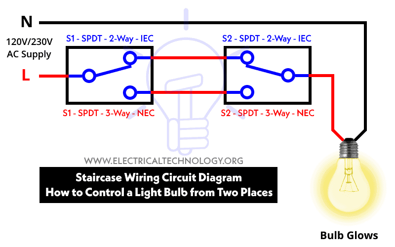
Staircase Wiring Circuit Diagram How To Control A Lamp
Electrical Wiring Systems And Methods Of Electrical Wiring

Intermediate Switch Its Construction Operation Uses

Electrical Technology Stair Case Wiring Wiring Diagram Or

3 Way Diagrams For Zen21 Zen22 Zen23 And Zen24 Ver 2 0
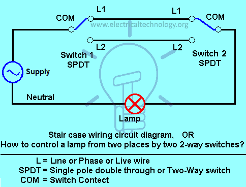
Staircase Wiring Circuit Diagram How To Control A Lamp

Electrical Diagrams And Schematics Wiki Odesie By Tech

Wiring Switches In Parallel Infinitybox
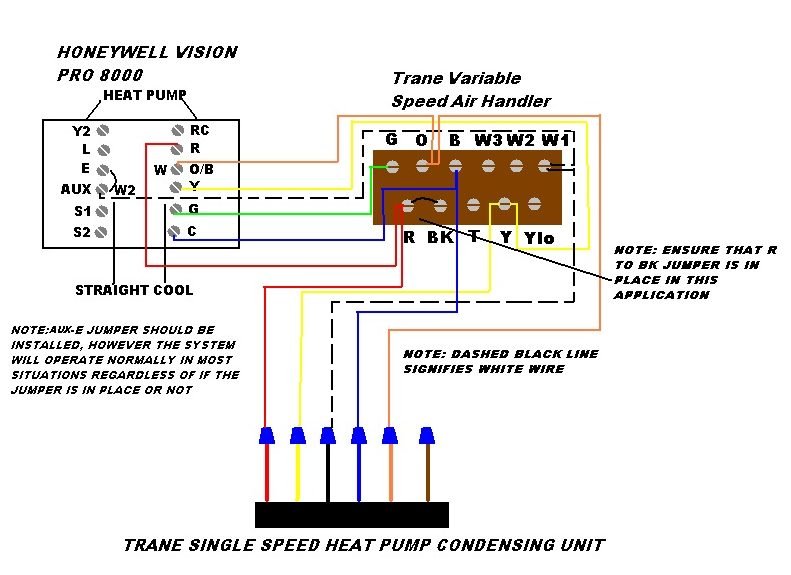
W1 W2 E Hvac School

3 Way Switch Wiring Methods Dead End And Radical S3

Wiring Diagram Illustrating The Connections Between The
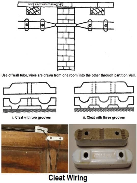
Types Of Wiring Systems And Methods Of Electrical Wiring

How To Read Automotive Wiring Diagrams Search Autoparts

Usb Wire Color Code And The Four Wires Inside Usb Wiring

Wiring Diagram Of V1 Microcircuit Different Connectivity

Different Electrical Tools On Circuit Diagram
